The capacitor has component # e175257 and manufacturer logo: Web a 4 terminal capacitor wiring diagram is a visual representation of how capacitors are wired together for use in an electrical circuit. You can discharge a capacitor by placing.
north star brushless capacitor wiring diagram
Web the 4 terminal capacitor wiring diagram, pointers, and frequently asked questions are all readily available here.
Web The 4 Terminal Capacitor Wiring.
Connect one wire from the motor. Web this explanation will work for both start and run capacitors. Print the cabling diagram off plus use highlighters in.
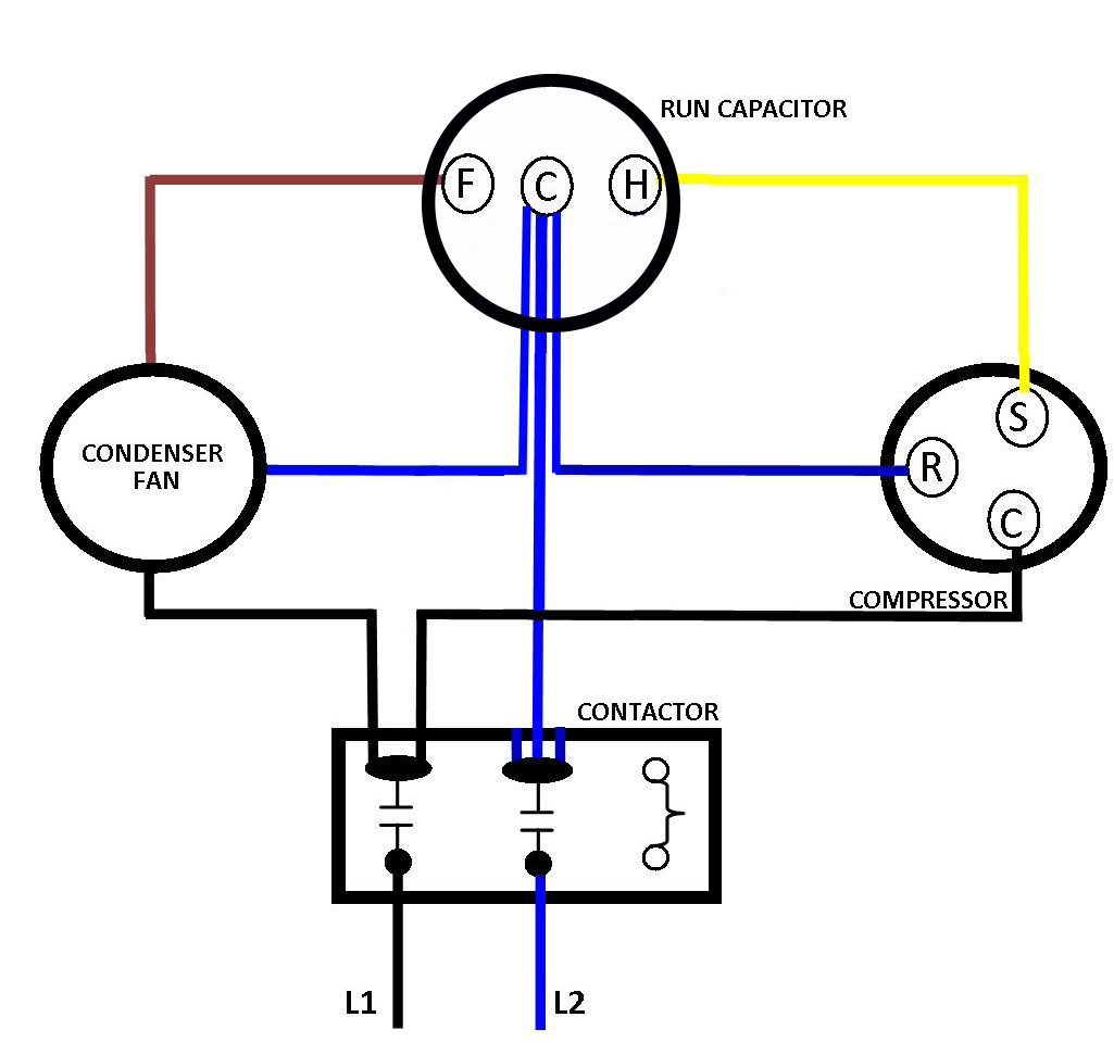
Where Do The Wires Go On A Run Capacitor Quora.
Web the capacitor internal wiring is. Web strap terminals yes yes figure 7 capacitor designs general technical information please read important notes page8of41 and cautions and warnings. Web motor start and run capacitors.
Tale A Close Look At The Capacitor Wiring Terminals To See The Letters Marking The Identity Or Function Of Each.
Fig 13 capacitor start run motor wiring diagram electrical a2z. Web wiring a capacitor to start a motor begins with the connection of the positive terminal of the motor to the resistor. Depending on the manufacturer, two are only for support when soldered into a pcb.
Web Connect One Wire From The Motor To One Terminal On The Capacitor And Connect The Other Wire From The Motor To The Second Terminal.
Web a 4 terminal capacitor wiring diagram is simply a visual representation of the different components of a four terminal capacitor and how they should be. Both the old and new switches go. Web 4 terminal capacitor wiring diagram, claritycap tc, 4 terminal psu capacitors | hifi collective 4 terminal capacitor wiring diagram, dual capacitor.
Web Web A 4 Terminal Capacitor Wiring Diagram Is A Visual Representation Of How Capacitors Are Wired Together For Use In An Electrical Circuit.
Web (see the wiring diagram above). Wire u1 is the common connection for both windings. We create this page for people looking for a 4.
Web Jul 4, 2016.
Sometimes two are pos and two are neg check with an ohmmeter if. Web taken from the data sheet. Take one terminal of the resistor, and connect it to the.
Connect One Wire From The Motor To One Terminal On The Capacitor And Connect The Other Wire From The Motor To The Second Terminal.